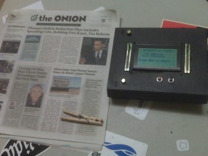
At the conclusion of UT’s embedded systems lab, EE445L, all student teams produce a final project of their own choosing. My partner (Tim) and I built a game system for playing Pong.
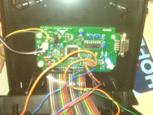
I designed the circuit schematic and wrote most of the software. Tim designed the PCB and assembled most of the hardware. Everything that could go wrong did, but we managed to build a fun little game.

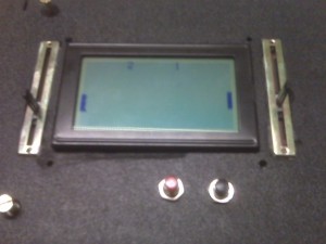
The interface is extremely intuitive. The potentiometers on either side of the screen control the paddles for each player. The code for the C32 is almost entirely C and was developed in Freescale’s CodeWarrior IDE.
The screen is an AGM1264 128×64 monochrome LCD. Professor Jonathan Valvano provides a useful driver for the c32 on his website. While the driver supports writing whole bitmaps, the memory layout of the LCD makes it very tricky to draw 2D shapes at arbitrary coordinates. I ended up using a 1-pixel ball because a 2×2 ball could require writes to 4 memory locations, a can of worms that I did not want to open.
But, if you’re interested in improving the game, you can draw to arbitrary pixels using the modulus arithmetic in drawBall(). It could easily be a jumping off point for a 2D graphics library supporting more interesting shapes. A word of warning: you will get a noticeable flicker when writing bitmaps quickly (we did 20 fps). The screen really isn’t built to draw every location continuously.
Edit: I had a conversation with another student who attributed the flicker to a call to LCD_Clear(0) in Valvano’s LCD_DrawImage routine. It’s there in LCD.c on line 383. I no longer have the hardware, but that would have been an easy fix to make.
Things that went wrong
- The seventh wire in the ribbon cable was broken, resulting in garbage on LCD. I tracked this down with a multimeter and patience.
- I forgot to right justify the 10-bit ADC inputs on the potentiometers. This should have been obvious when the values read were greater than 1023. The fix: ATDCTL5= channel + 0x80;
- The original box we ordered was just barely too small. Tim measured the LCD’s bezel, rather than its slightly wider PCB. I didn’t double check it. We ended up using the obnoxiously large black box in the picture.
- The black button unexpectedly employed negative logic. That is, pressing it opens the circuit. This was trivial to deal with in software, but annoying nonetheless.
- The power switch broke. Our nice metal toggle switch broke into pieces when I bumped it on the table. I decided to short the wires in the interest of time.
- Tim was unaware that capacitors may be polarized and soldered them in randomly. He is now very good with solder wick.
- The potentiometers are a little longer than the screen is wide. It would be better to have a perfect 1:1 correspondence.
- There is a strange bug with the LCD hardware or driver that causes a few pixels near the lower left corner to erroneously become dark. Hence the name, “Distortion Pong”. I tried to convince the TA it was feature, but I don’t think he bought it.
Check out the hastily written source.
This project wouldn’t have been possible without the technical guidance of Darryl Goodnight, Paul Landers, and Justin Capogna.
If this post tickled your fancy, check out my Java version of pong. The functionality is nearly identical, but the code is much nicer.

